
2026 How to Choose the Right Festo Pneumatic Cylinder?
Choosing the right Festo Pneumatic Cylinder in 2026 requires more than comparing bore sizes and prices. The decision affects speed, repeatability, energy use, noise, and maintenance access. A cylinder moving a 20-kilogram fixture behaves differently from one opening a lightweight packaging gate. Stroke length, mounting style, load direction, cushioning, operating pressure, and duty cycle must match the real machine.
Industrial automation continues to expand. The International Federation of Robotics reported 541,302 industrial robots installed worldwide in 2023, showing sustained demand for precise motion systems. The 2024 World Robotics report also highlights manufacturing pressure to improve productivity and flexibility. Pneumatic actuators remain valuable because they are compact, fast, and comparatively simple to service. Festo’s ISO 15552-compatible cylinders also support standardized machine design, but compatibility alone does not guarantee a correct selection. Peter Post, a Festo technology executive, has stated, “Pneumatics remains a key technology for industrial automation.” That view is practical, not absolute. Electric actuators may suit applications needing programmable positioning or lower compressed-air consumption. The wrong technology can be expensive.
This guide examines cylinder types, force calculations, installation conditions, sensor options, and lifecycle costs. It also considers leakage, contamination, temperature, and imperfect alignment. Those details are easy to overlook. Yet they often determine whether a cylinder lasts for years or requires early replacement. Reports from MarketsandMarkets and Grand View Research indicate continued growth in the global pneumatic equipment market, although their forecasts differ by methodology. That uncertainty deserves attention. Choose from measured operating data, not marketing language. Test the final configuration under actual load.
Understanding Festo Pneumatic Cylinder Types and Applications
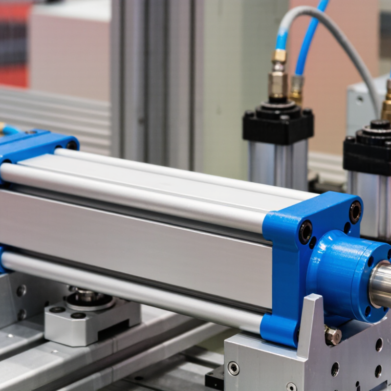
Choosing a pneumatic cylinder begins with understanding how each type behaves in real equipment. A single-acting cylinder uses air in one direction and a spring for return. It suits clamps, stops, and light positioning tasks. A double-acting cylinder uses air for extension and retraction. It offers better control for slides, grippers, and repeated production movements. Compact cylinders save space, while guided cylinders resist side loads during pressing or handling.
Rodless cylinders move a carriage along the barrel. They work well in long conveyor transfers and limited installation spaces. Rotary actuators convert air pressure into angular motion for valve control or part turning. For dusty areas, sealed designs deserve closer attention. For wet washdown zones, corrosion resistance and suitable seals matter more than appearance.
In field commissioning, I check the load, stroke, cycle rate, and available pressure before selecting a cylinder. The required force is not just the load weight. Friction, acceleration, and a safety margin also affect sizing. A vertical application needs special care because the load can drop when air pressure disappears. Add mechanical support when gravity creates a hazard. Adjustable cushioning can reduce end-of-stroke impact, but it cannot fix a badly oversized cylinder. I once focused too much on bore diameter and overlooked mounting flexibility. That mistake caused vibration at the rod end. Measure the actual space, inspect the air quality, and verify the mounting standard before ordering. Small details matter.
How to Choose the Right Pneumatic Cylinder? – Understanding Pneumatic Cylinder Types and Applications
| Cylinder Type | Operating Principle | Typical Motion and Stroke | Recommended Applications | Main Advantages | Key Selection Considerations |
|---|---|---|---|---|---|
| Single-Acting Cylinder | Compressed air drives the piston in one direction; a spring provides the return stroke. | Linear motion; generally suited to shorter strokes because spring force increases with compression. | Clamping, ejecting, stopping, indexing, and simple push-return mechanisms. | Simple control, reduced air consumption during return, and fail-return capability in some designs. | Check available spring force, required return speed, load direction, and usable stroke. |
| Double-Acting Cylinder | Compressed air controls both extension and retraction through separate ports. | Linear motion; available in a broad range of bore sizes and stroke lengths. | Material handling, pressing, lifting, feeding, automation fixtures, and machine tooling. | Positive control in both directions and better suitability for adjustable speed and position control. | Size the bore for force, the rod for buckling and side load, and the valve for required flow. |
| Compact Cylinder | A shortened body provides linear actuation where installation space is limited. | Linear motion; typically used for short to medium strokes. | Small assembly machines, clamping stations, inspection equipment, and compact transfer units. | Space-efficient design and low installation height. | Confirm available force, port orientation, mounting space, and resistance to side loading. |
| Guided Cylinder | A cylinder is combined with guide rods or a guided slide to constrain rotation and absorb external loads. | Straight linear motion; stroke is selected according to the required travel. | Gripping, transferring, lifting, pressing, and applications with off-center or moment loads. | Improved alignment, higher resistance to rotation, and better handling of side loads than a standard rod cylinder. | Review allowable moment, guide clearance, load position, and maintenance requirements. |
| Rodless Cylinder | A piston transfers force to an external carriage without requiring a projecting piston rod. | Linear motion; useful for long travel within a compact longitudinal envelope. | Long-stroke transfer systems, pick-and-place units, positioning, and door or gate movement. | Efficient use of space and reduced risk of rod bending over long travel distances. | Select the sealing or magnetic coupling design carefully and provide external guidance for side loads. |
| Telescopic Cylinder | Multiple concentric stages extend to create a long stroke from a short retracted length. | Linear motion; long extension with a comparatively short closed length. | Space-restricted lifting, tipping, access mechanisms, and specialized handling equipment. | High stroke-to-retracted-length ratio. | Consider reduced stability at full extension, stage sequencing, load alignment, and available mounting space. |
| Rotary Pneumatic Actuator | Pneumatic pressure produces limited-angle shaft rotation rather than linear rod travel. | Angular motion; common rotation ranges include 90°, 180°, or other specified angles. | Valve operation, part turning, indexing, diverter mechanisms, and robotic gripper rotation. | Compact angular actuation and fast repeatable movement. | Check torque at the required pressure, inertia of the load, stopping method, and allowable shaft moment. |
Practical Sizing and Selection Criteria
| Selection Dimension | What to Determine | Useful Guidance | Common Design Risk |
|---|---|---|---|
| Required Force | The force needed to move, hold, clamp, or lift the load. | Theoretical extension force is approximately F = P × A, where pressure is multiplied by piston area. Allow for friction and a safety margin. | Selecting a bore from static load only while ignoring acceleration, friction, or pressure losses. |
| Bore and Rod Diameter | The piston diameter determines force; the rod diameter affects strength and retraction force. | Retraction force is lower than extension force because the rod reduces effective piston area. | Rod buckling, bending, or premature seal wear caused by excessive unsupported load. |
| Stroke Length | The distance the actuator must travel to complete the task. | Use the shortest practical stroke and provide end-of-stroke clearance where required. | Impact at the end of travel, insufficient positioning range, or excessive rod deflection. |
| Speed and Air Flow | Required extension and retraction time, including load inertia. | Speed depends on air flow, valve capacity, tubing, pressure, load, and exhaust restrictions. Use flow controls for adjustment. | Oversized tubing or an undersized valve causing slow response and unstable motion. |
| Cushioning | Whether the piston needs controlled deceleration near the end of the stroke. | Adjustable pneumatic cushioning is useful for higher speeds or heavier loads; external shock absorbers may be needed for severe impacts. | Mechanical impact, noise, vibration, and shortened service life. |
| Environment | Temperature, moisture, dust, chemicals, washdown exposure, and cleanliness requirements. | Choose compatible seals, materials, corrosion protection, and ingress protection for the installation environment. | Seal degradation, corrosion, contamination, or loss of lubrication. |
| Mounting and Alignment | Available space, mounting orientation, pivot requirements, and alignment accuracy. | Use suitable brackets, clevises, trunnions, or guided designs; avoid using the piston rod as a structural guide. | Side loading, uneven wear, rod scoring, and seal leakage. |
Note: Final cylinder selection should be verified against the manufacturer’s technical data, operating pressure, duty cycle, load profile, installation conditions, and applicable machinery safety requirements.